I often get questions on how to get started in IoT pentesting or hardware hacking. My usual suggestion is just to grab a device, open it up, and dive in! Recently, I acquired an interesting security camera in my travels to Southeast Asia: the VStarcam CB73. I thought this camera would be an excellent target for reverse engineering and hunting for security vulnerabilities.
我经常收到有关如何开始物联网渗透测试或硬件黑客攻击的问题。我通常的建议是拿起一个设备,打开它,然后投入使用!最近,我在东南亚旅行时购买了一款有趣的安全摄像机:VStarcam CB73。我认为这款相机将成为逆向工程和寻找安全漏洞的绝佳目标。
We can see in the image below that this is an extremely small camera, about 1 square inch in size.
从下图中我们可以看到,这是一个非常小的相机,大小约为 1 平方英寸。
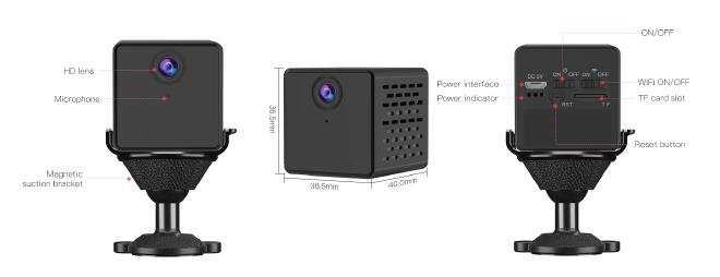
VStarcam CB73 – 一款超小型 WiFi 安全摄像头
This device connects to the internet using WiFi and uses a mobile application to interact with the camera. In fact one of the reasons I’m targeting this device is because in its marketing material it boasts being able to view the camera video feed and receive alerts from anywhere using the mobile application. This tells me that the device communicates with a cloud server somewhere. As a hacker, I LOVE it when devices have complexity. The more complex the device is, the larger the attack surface and the higher likelihood that I will find some cool vulnerabilities.
该设备使用 WiFi 连接到互联网,并使用移动应用程序与相机交互。事实上,我瞄准该设备的原因之一是因为在其营销材料中,它声称能够使用移动应用程序查看摄像头视频并从任何地方接收警报。这告诉我该设备与某处的云服务器进行通信。作为一名黑客,我喜欢设备的复杂性。设备越复杂,攻击面就越大,我发现一些很酷的漏洞的可能性就越大。
Device Analysis 设备分析
#
The first thing to do with any IoT device is to open it up and pull out all of the Printed Circuit Boards (PCBs) and other connected components. After taking out a couple screws, and prying open the outer casing, we are able to remove the main PCB and the battery.
对于任何物联网设备,要做的第一件事就是打开它并拉出所有印刷电路板 (PCB) 和其他连接的组件。取下几颗螺丝,撬开外壳后,我们就可以取下主PCB和电池了。
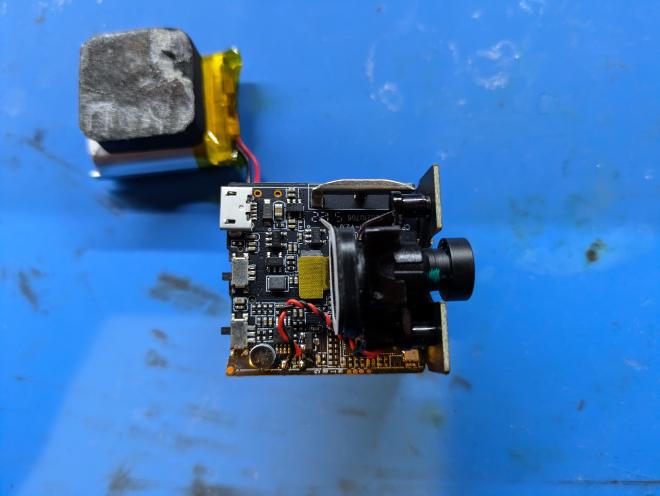
Vstarcam CB73 的内部结构
On the top side of the device PCB we can see a micro USB connector, two switches (one for power, one for WiFi), A Chip labeled “Ingenic T31” hiding behind the camera, and a set of 4 test pads labeled “G”, “R”, “T”, “N”. The two things on this side of the board that interest me most are the T31 chip and the 4 labeled test pads.
在设备 PCB 的顶部,我们可以看到一个微型 USB 连接器、两个开关(一个用于电源,一个用于 WiFi)、隐藏在相机后面标有“Ingenic T31”的芯片以及一组标有“G”的 4 个测试垫”、“R”、“T”、“N”。电路板这一侧最让我感兴趣的两件事是 T31 芯片和 4 个标记的测试垫。
With a bit of internet searching, we can read about the Ingenic T31 chip and understand it’s a module that has a MIPS CPU, onboard memory, and video encoding capabilities all in a single silicon package.
通过一些互联网搜索,我们可以了解君正 T31 芯片,并了解它是一个在单个硅封装中具有 MIPS CPU、板载内存和视频编码功能的模块。
However the most interesting part of the top of the PCB are the labeled test pads. To a seasoned IoT hacker, it was immediately obvious that these test pads were UART. UART is a serial communication protocol that is often used on Linux IoT devices to provide developers access to the device console for debugging purposes. We will return to this UART interface in a bit.
然而,PCB 顶部最有趣的部分是标记的测试焊盘。对于经验丰富的物联网黑客来说,很明显这些测试板是 UART。 UART 是一种串行通信协议,通常在 Linux IoT 设备上使用,让开发人员能够访问设备控制台以进行调试。我们稍后会回到这个 UART 接口。
On the bottom side of the device PCB we see the WiFi module, an SDcard slot, and an 8-pin SPI flash chip. Here the flash chip, labeled “25QH64CHIQ”, is clearly the most interesting item. This will be where the device firmware is stored.
在设备PCB的底部,我们看到WiFi模块、SD卡插槽和8针SPI闪存芯片。这里,标记为“25QH64CHIQ”的闪存芯片显然是最有趣的项目。这将是存储设备固件的位置。
Firmware Extraction 固件提取
#
Now that we have identified the SPI flash chip we will remove the chip from the PCB and read out the firmware so we can analyze it for security issues.
现在我们已经识别了 SPI 闪存芯片,我们将从 PCB 上取下该芯片并读出固件,以便分析它的安全问题。
In order to remove the SPI flash chip, we will use a hot air rework station.
为了去除SPI闪存芯片,我们将使用热风返修台。
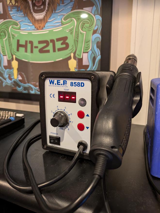
我的热风返修站
I usually set my hot air station temperature to 465 Celsius (869 Fahrenheit) and set the airspeed to somewhere in the middle range. Then blast the flash chip with hot air and be patient! we don’t want to pull the chip off too fast and rip any of the pads that connect the chip to the PCB off the board.
我通常将热空气站温度设置为 465 摄氏度(869 华氏度),并将空速设置为中间范围。然后用热风吹闪存芯片,要有耐心!我们不想太快地将芯片拉下来,从而将连接芯片和 PCB 的任何焊盘从电路板上撕下来。
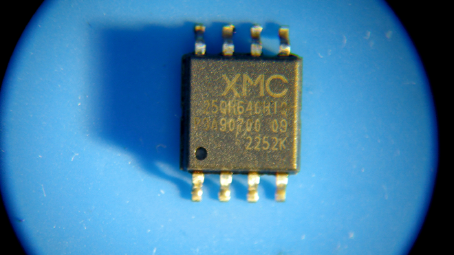
从 PCB 上拆下后的 XMC 25QH64C SPI 闪存芯片
Once the chip is off, we put it into our XGecu T56 universal programmer with the correctly sized socket.
芯片关闭后,我们将其放入具有正确尺寸插座的 XGecu T56 通用编程器中。
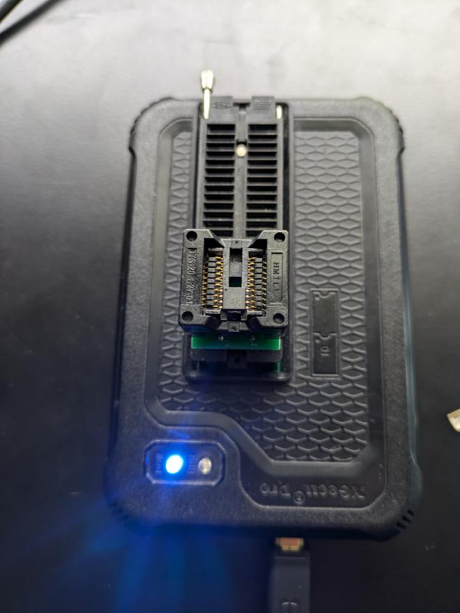
SPI闪存芯片放入XGecu T56通用编程器中
Now with the SPI flash chip placed into the XGecu T56 we need to run its Windows-only Xgpro software. we can either run it directly on Windows or under Linux with the help of Wine. In Wine, we need to use a special DLL provided by radiomanV’s TL866 project on GitHub.
现在,将 SPI 闪存芯片放入 XGecu T56 后,我们需要运行其仅适用于 Windows 的 Xgpro 软件。我们可以直接在 Windows 上运行它,也可以借助 Wine 在 Linux 下运行它。在Wine中,我们需要使用GitHub上radiomanV的TL866项目提供的特殊DLL。
First we search for our flash chip in the “Search Device” menu.
首先我们在“搜索设备”菜单中搜索我们的闪存芯片。
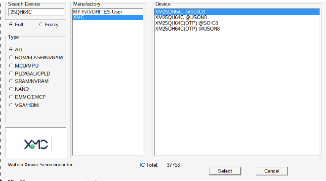
在XGpro中选择25QH64C设备
Then we then perform the READ operation.
然后我们再执行READ操作。
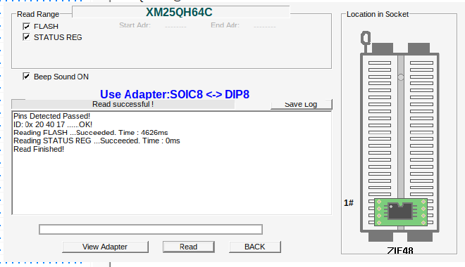
在 XGpro 中执行 READ 操作
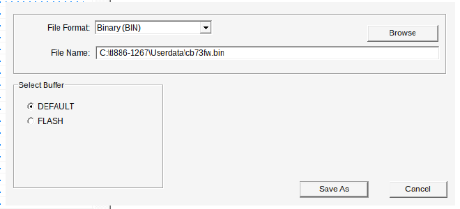
Finally, we save the file as “cb73fw.bin”.
最后,我们将文件保存为“cb73fw.bin”。
After we have successfully read the contents of the flash chip we use our hot air rework station to reattach the 8-pin SPI flash chip to the device PCB.
成功读取闪存芯片的内容后,我们使用热风返修站将 8 引脚 SPI 闪存芯片重新连接到设备 PCB。
UART Console 串口控制台
#
Now we turn our attention back to the UART interface we discovered on 4 test pads on the top side of the PCB.
现在我们将注意力转回我们在 PCB 顶部的 4 个测试焊盘上发现的 UART 接口。
First, while the device is powered on, we use a multimeter to measure the voltage by touching the black multimeter probe to the GND test pad (labeled as “G”) and the red probe to either the TX test pad (labeled as “T”) or VCC test pad (labeled as “N”). We read a voltage of 3.3v which is the most common UART voltage on Linux IoT devices. We will use a FTDI TTL-232R-3V3 cable to connect to our PC.
首先,当设备开机时,我们使用万用表测量电压,将黑色万用表探头接触 GND 测试焊盘(标记为“G”),将红色探头接触 TX 测试焊盘(标记为“T”) ”)或 VCC 测试焊盘(标记为“N”)。我们读取到的电压为 3.3v,这是 Linux IoT 设备上最常见的 UART 电压。我们将使用 FTDI TTL-232R-3V3 电缆连接到我们的 PC。
By reviewing the TTL-232R-3V3 Datasheet we find the cable pinout shown below.
通过查看TTL-232R-3V3 数据表,我们发现电缆引脚排列如下所示。
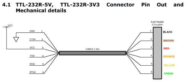
3.3v UART 转 USB 电缆引脚排列
One thing to be aware of is that when connecting the TX and RX wires from a target device to the cable, the signals need to be reversed. So the TX from the device needs to connect to the RX on the cable, and visa versa. This gives us the following wire connections:
需要注意的一件事是,当将 TX 和 RX 线从目标设备连接到电缆时,信号需要反转。因此,设备的 TX 需要通过电缆连接到 RX,反之亦然。这为我们提供了以下接线:
| Device Pad 设备垫 | UART Cable Pin UART 电缆引脚 | UART Cable Color UART 电缆颜色 |
|---|---|---|
| TX | RX | Yellow 黄色的 |
| RX | TX | Orange 橙子 |
| GND | GND | Black 黑色的 |
Now the question is: how do we get these 3 wires connected to those tiny test pads? First off, we don’t need to connect specifically to the GND test pad, we can find a more convient spot on the board to connect to Ground. In our case, we decided to connect an alligator clip to the WiFi antenna.
现在的问题是:我们如何将这 3 条线连接到那些微小的测试垫上?首先,我们不需要专门连接到 GND 测试焊盘,我们可以在板上找到一个更方便的点来连接到地。在我们的例子中,我们决定将鳄鱼夹连接到 WiFi 天线。
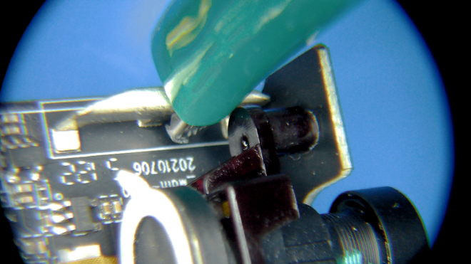
连接至 WiFi 天线的鳄鱼夹
This just leaves us with 2 test pads we need to connect to our UART adapter. One method would be to solder some small wires to the test pads. This requires us to have some decent soldering equipment and to be careful not to rip the test pads off the PCB. Instead, for this task we will use our PCBite probes. These probes have a small needle on the end that is spring-loaded. This allows us to carefully rest the probe on the test pad.
这只剩下 2 个需要连接到 UART 适配器的测试垫。一种方法是将一些小电线焊接到测试焊盘上。这要求我们拥有一些像样的焊接设备,并小心不要将测试焊盘从 PCB 上撕下来。相反,对于此任务,我们将使用 PCBite 探针。这些探头的末端有一根装有弹簧的小针。这使我们能够小心地将探针放在测试垫上。
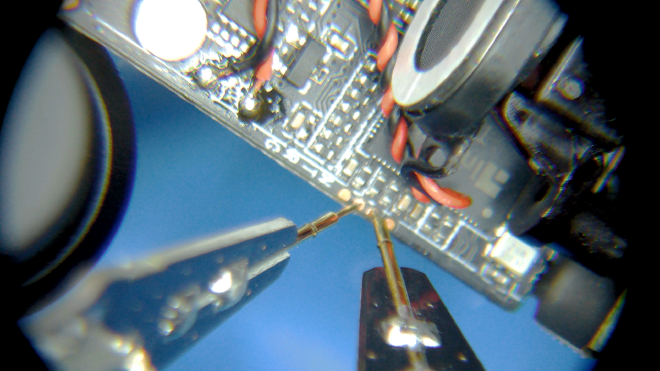
连接到小测试焊盘的 PCBite 探针
Now with our UART adapter plugged into our Linux computer, we run the following:
现在,我们的 UART 适配器已插入 Linux 计算机,我们运行以下命令:
picocom -b 115200 /dev/ttyUSB0
Picocom is a terminal emulator that will allow us to send and receive serial data over our UART cable. 115200 is the most common baud rate (bits transmitted per second) that one will find on IoT devices. In this case, our guess turns out to be correct. “/dev/ttyUSB0” is where our USB device gets mapped to on our Linux computer.
Picocom 是一个终端仿真器,允许我们通过 UART 电缆发送和接收串行数据。 115200 是物联网设备上最常见的波特率(每秒传输的位数)。在这种情况下,我们的猜测被证明是正确的。 “/dev/ttyUSB0”是我们的 USB 设备在 Linux 计算机上映射到的位置。
Now that picocom is running, we can power on our device and observe the Linux console log during boot up. I make a habit of copying all of the output of the UART console on device boot up into a text file for reviewing later.
现在picocom正在运行,我们可以打开设备电源并在启动过程中观察 Linux 控制台日志。我习惯将设备启动时 UART 控制台的所有输出复制到文本文件中,以便稍后查看。
U-Boot SPL 2013.07-00014-g7e49a25-dirty (Jul 15 2022 - 19:00:08)
[ ---------- TRUNCATED ---------- ]
U-Boot 2013.07 (Aug 30 2022 - 17:52:01)
[ ---------- TRUNCATED ---------- ]
Hit any key to stop autoboot:  0
the manufacturer 20
SF: Detected XM25QH64C

--->probe spend 4 ms
SF: 2097152 bytes @ 0x40000 Read: OK
--->read spend 675 ms
## Booting kernel from Legacy Image at 80600000 ...
   Image Name:   Linux-3.10.14__isvp_swan_1.0__
   Image Type:   MIPS Linux Kernel Image (lzma compressed)
   Data Size:    1480678 Bytes = 1.4 MiB
   Load Address: 80010000
   Entry Point:  803283a0
   Verifying Checksum ... OK
   Uncompressing Kernel Image ... OK
[ ---------- TRUNCATED ---------- ]
veepai login:
Notice that the UART console after the system has fully booted prompts us for a login. Currently we don’t have the username and password and therefore can not login.
请注意,系统完全启动后,UART 控制台会提示我们登录。目前我们没有用户名和密码,因此无法登录。
Bootloader Menu to Shell 引导加载程序菜单到 Shell
#
After we allow the device to boot up once without interruption, we want to see if the bootloader allows us to enter its bootloader menu. To do this, we power the device off, hold down the enter key in our picocom window, and then power the device on again. This causes the boot process to stop and enter the U-Boot bootloader menu:
当我们允许设备不间断地启动一次后,我们想看看引导加载程序是否允许我们进入其引导加载程序菜单。为此,我们关闭设备电源,按住picocom窗口中的 Enter 键,然后再次打开设备电源。这会导致引导过程停止并进入 U-Boot 引导加载程序菜单:
[ ---------- TRUNCATED ---------- ]
Hit any key to stop autoboot:  0
isvp_t31#
isvp_t31#
isvp_t31#
In this bootloader menu we can run the help command to show what commands are supported on a specific device. This is helpful because when device developers compile U-Boot they have many optional utilities that may or may not be included in any specific build.
在此引导加载程序菜单中,我们可以运行help命令来显示特定设备支持哪些命令。这很有用,因为当设备开发人员编译 U-Boot 时,他们有许多可选实用程序,这些实用程序可能包含也可能不包含在任何特定构建中。
isvp_t31# help
?       - alias for 'help'
boot    - boot default, i.e., run 'bootcmd'
boota   - boot android system
bootd   - boot default, i.e., run 'bootcmd'
bootm   - boot application image from memory
bootp   - boot image via network using BOOTP/TFTP protocol
chpart  - change active partition
coninfo - print console devices and information
echo    - echo args to console
env     - environment handling commands
ethphy  - ethphy contrl
fatinfo - print information about filesystem
fatload - load binary file from a dos filesystem
fatls   - list files in a directory (default /)
getadc  - get adc val elapsed,

gettime - get timer val elapsed,

go      - start application at address 'addr'
help    - print command description/usage
loadb   - load binary file over serial line (kermit mode)
loads   - load S-Record file over serial line
loady   - load binary file over serial line (ymodem mode)
mmc     - MMC sub system
mmcinfo - display MMC info
mtdparts- define flash/nand partitions
printenv- print environment variables
reset   - Perform RESET of the CPU
run     - run commands in an environment variable
saveenv - save environment variables to persistent storage
setenv  - set environment variables
sf      - SPI flash sub-system
sleep   - delay execution for some time
source  - run script from memory
tftpboot- boot image via network using TFTP protocol
version - print monitor, compiler and linker version
watchdog- open or colse the watchdog
The first command we will run will be the printenv command. This will print out the currently loaded U-Boot environmental variables. When doing this we see the following output:
我们将运行的第一个命令是printenv命令。这将打印出当前加载的 U-Boot 环境变量。执行此操作时,我们会看到以下输出:
isvp_t31# printenv
adcthreshold=1240
baudrate=115200
bootargs=console=ttyS1,115200n8 quiet mem=42M@0x0 rmem=22M@0x2A00000 init=/linuxrc rootfstype=squashfs root=/dev/mtdblock2 rw mtdparts=jz_sfc:256k(boot),1536k(kernel),4608k(root),1792k(appfs),8m@0(all)
bootcmd=sf probe;sf read 0x80600000 0x40000 0x200000; bootm 0x80600000
bootdelay=1
ethact=Jz4775-9161
ethaddr=00:d0:d0:00:95:27
gatewayip=192.168.1.1
ipaddr=192.168.1.126
loads_echo=1
netmask=255.255.255.0
serverip=192.168.1.101
stderr=serial
stdin=serial
stdout=serial

Environment size: 537/16380 bytes
The main environmental variable that I am interested is bootargs:
我感兴趣的主要环境变量是bootargs :
bootargs=console=ttyS1,115200n8 quiet mem=42M@0x0 rmem=22M@0x2A00000 init=/linuxrc rootfstype=squashfs root=/dev/mtdblock2 rw mtdparts=jz_sfc:256k(boot),1536k(kernel),4608k(root),1792k(appfs),8m@0(all)
bootargs=console=ttyS1,115200n8 安静 mem=42M@0x0 rmem=22M@0x2A00000 init=/linuxrc rootfstype=squashfs root=/dev/mtdblock2 rw mtdparts=jz_sfc:256k(启动),1536k(内核),4608k(根) ,1792k(appfs),8m@0(全部)
Notice the part init=/linuxrc of the bootargs variable. This parameter is telling the Linux kernel how to execute the Init System, which is the first process started by the Linux kernel after the system boots up. On this device. and most IoT devices, this init system is provided by BusyBox. This init system will perform various actions like mounting filesystems other than the root filesystem, and running the login program on the UART console. We can modify the init system from init=/linuxrc to init=/bin/sh to drop into a shell on boot instead of the default init system. To do this, we use the following setenv command:
注意 bootargs 变量的init=/linuxrc部分。该参数告诉Linux内核如何执行Init System ,它是Linux内核在系统启动后启动的第一个进程。在此设备上。和大多数 IoT 设备一样,这个 init 系统是由 BusyBox 提供的。该初始化系统将执行各种操作,例如安装除根文件系统之外的文件系统,以及在 UART 控制台上运行login程序。我们可以将 init 系统从init=/linuxrc修改为init=/bin/sh以在启动时进入 shell,而不是默认的 init 系统。为此,我们使用以下setenv命令:
setenv bootargs console=ttyS1,115200n8 quiet mem=42M@0x0 rmem=22M@0x2A00000 init=/bin/sh rootfstype=squashfs root=/dev/mtdblock2 rw mtdparts=jz_sfc:256k(boot),1536k(kernel),4608k(root),1792k(appfs),8m@0(all)
Then we run the boot command to boot the device using our new environment variable:
然后我们运行boot命令以使用新的环境变量启动设备:
isvp_t31# boot
the manufacturer 20
SF: Detected XM25QH64C

--->probe spend 4 ms
SF: 2097152 bytes @ 0x40000 Read: OK
--->read spend 675 ms
## Booting kernel from Legacy Image at 80600000 ...
   Image Name:   Linux-3.10.14__isvp_swan_1.0__
   Image Type:   MIPS Linux Kernel Image (lzma compressed)
   Data Size:    1480678 Bytes = 1.4 MiB
   Load Address: 80010000
   Entry Point:  803283a0
   Verifying Checksum ... OK
   Uncompressing Kernel Image ... OK

Starting kernel ...

[    0.000000] Initializing cgroup subsys cpu
[    0.000000] Initializing cgroup subsys cpuacct
[    0.000000] Linux version 3.10.14__isvp_swan_1.0__ (madong@vstarcam) (gcc version 4.7.2 (Ingenic r2.3.3 2016.12) ) #7 PREEMPT Tue Aug 30 16:11:27 CST 2022
[    0.000000] bootconsole [early0] enabled
[    0.000000] CPU0 RESET ERROR PC:DA64E93C
[    0.000000] CPU0 revision is: 00d00100 (Ingenic Xburst)
[    0.000000] FPU revision is: 00b70000
[    0.000000] CCLK:1104MHz L2CLK:552Mhz H0CLK:250MHz H2CLK:250Mhz PCLK:125Mhz
[    0.000000] Determined physical RAM map:
[    0.000000]  memory: 00429000 @ 00010000 (usable)
[    0.000000]  memory: 00037000 @ 00439000 (usable after init)
[    0.093754] drivers/rtc/hctosys.c: unable to open rtc device (rtc0)
/bin/sh: can't access tty; job control turned off
/ #
We then have to run a few commands to get the /system partition mounted:
然后我们必须运行一些命令来安装 /system 分区:
mount -t proc proc /proc
mount -t tmpfs tmpfs /dev
mount -a
echo /sbin/mdev > /proc/sys/kernel/hotplug
/sbin/mdev -s
mount -t jffs2 /dev/mtdblock3 /system
Lets take a look at the /etc/passwd file:
让我们看一下/etc/passwd文件:
~ # ls -l /etc/passwd
lrwxrwxrwx    1 1001     1001            20 Jun 16  2021 /etc/passwd -> /system/param/passwd
Notice that /etc/passwd is a symlink to /system/param/passwd. Why is it a symlink? Let’s check the mount command:
请注意, /etc/passwd是/system/param/passwd的符号链接。为什么它是符号链接?我们来检查一下mount命令:
~ # mount
rootfs on / type rootfs (rw)
/dev/root on / type squashfs (ro,relatime)
proc on /proc type proc (rw,relatime)
tmpfs on /dev type tmpfs (rw,relatime)
tmpfs on /tmp type tmpfs (rw,relatime)
tmpfs on /run type tmpfs (rw,nosuid,nodev,relatime,mode=755)
sysfs on /sys type sysfs (rw,relatime)
/dev/mtdblock3 on /system type jffs2 (rw,relatime)
Notice that the first line showns us that the root filesystem, mounted on /, is read-only. In fact another way we know this partition is read-only is because it is a SquashFS filesystem. SquashFS, by its design, can’t be mounted with write permissions. So if the developers of the system want something to be writable that normally would live in the root filesystem, they instead make the file in the root filesystem a symlink to a writable file in the JFFS2 partition mounted on /system.
请注意,第一行向我们显示安装在/上的根文件系统是只读的。事实上,我们知道该分区是只读的另一种方式是因为它是 SquashFS 文件系统。根据其设计,SquashFS 无法以写入权限挂载。因此,如果系统开发人员希望根文件系统中的某些内容可写,他们会将根文件系统中的文件设置为指向/system上挂载的 JFFS2 分区中可写文件的符号链接。
We can now obtain the administrative user’s password hash:
我们现在可以获得管理用户的密码哈希:
# cat /etc/passwd
vstarcam2017:uTV43RfKc73oM:0:0:Administrator:/:/bin/sh
I attempted to crack this password hash with hashcat against multiple wordlists without success:
我尝试使用 hashcat 针对多个单词列表破解此密码哈希,但没有成功:
echo 'uTV43RfKc73oM' > hash.txt
hashcat -m500 hash.txt wordlist1.txt wordlist2.txt ...
Let’s see if we can figure out the password another way…
让我们看看是否可以通过其他方式找出密码……
Firmware Analysis 固件分析
#
We will now return to the firmware we read off of the SPI flash chip. Let’s use binwalk to extract any filesystems that we can from the firmware image:
现在我们将返回到从 SPI 闪存芯片读取的固件。让我们使用binwalk从固件映像中提取我们可以提取的任何文件系统:
$ binwalk -e cb73fw.bin

DECIMAL       HEXADECIMAL     DESCRIPTION
--------------------------------------------------------------------------------
48253         0xBC7D          JBOOT STAG header, image id: 2, timestamp 0x1400A420, image size: 554991616 bytes, image JBOOT checksum: 0xA020, header JBOOT checksum: 0x400
125385        0x1E9C9         JBOOT STAG header, image id: 2, timestamp 0x18A3A200, image size: 682602496 bytes, image JBOOT checksum: 0xA400, header JBOOT checksum: 0x2127
127813        0x1F345         JBOOT STAG header, image id: 2, timestamp 0xB024318, image size: 4278207360 bytes, image JBOOT checksum: 0x620F, header JBOOT checksum: 0x432
129749        0x1FAD5         JBOOT STAG header, image id: 5, timestamp 0x250411FA, image size: 537010824 bytes, image JBOOT checksum: 0xBC00, header JBOOT checksum: 0x218F
164817        0x283D1         JBOOT STAG header, image id: 3, timestamp 0xA004918, image size: 553722640 bytes, image JBOOT checksum: 0x4018, header JBOOT checksum: 0x2B00
186521        0x2D899         JBOOT STAG header, image id: 3, timestamp 0xD006210, image size: 2148810752 bytes, image JBOOT checksum: 0x9980, header JBOOT checksum: 0x308F
190224        0x2E710         CRC32 polynomial table, little endian
194484        0x2F7B4         LZO compressed data
197912        0x30518         Android bootimg, kernel size: 0 bytes, kernel addr: 0x70657250, ramdisk size: 543519329 bytes, ramdisk addr: 0x6E72656B, product name: "mem boot start"
262144        0x40000         uImage header, header size: 64 bytes, header CRC: 0xC5F74AE8, created: 2022-08-30 08:11:32, image size: 1480678 bytes, Data Address: 0x80010000, Entry Point: 0x803283A0, data CRC: 0x42B2FB8A, OS: Linux, CPU: MIPS, image type: OS Kernel Image, compression type: lzma, image name: "Linux-3.10.14__isvp_swan_1.0__"
262208        0x40040         LZMA compressed data, properties: 0x5D, dictionary size: 67108864 bytes, uncompressed size: -1 bytes
1301640       0x13DC88        JBOOT STAG header, image id: 14, timestamp 0xEA9BD3FE, image size: 3424185437 bytes, image JBOOT checksum: 0x9F9A, header JBOOT checksum: 0xD67
1835008       0x1C0000        Squashfs filesystem, little endian, version 4.0, compression:xz, size: 4680592 bytes, 376 inodes, blocksize: 65536 bytes, created: 2022-04-08 13:34:09
6553612       0x64000C        JFFS2 filesystem, little endian
6586448       0x648050        Zlib compressed data, compressed
6586552       0x6480B8        JFFS2 filesystem, little endian
6587300       0x6483A4        Zlib compressed data, compressed
[ ---------- TRUNCATED ---------- ]
Looking inside the _cb73fw.bin.extracted directory that binwalk created, we can see a large amount of file and directories.
查看binwalk创建的_cb73fw.bin.extracted目录,我们可以看到大量的文件和目录。
$ ls -l _cb73fw.bin.extracted/
total 657080
-rw-r--r--  1 nmatt nmatt 4680592 Jul 26 15:18 1C0000.squashfs
[ ---------- TRUNCATED ---------- ]
drwxr-xr-x  6 nmatt nmatt    4096 Jul 26 15:18 jffs2-root
drwxr-xr-x  6 nmatt nmatt    4096 Jul 26 15:18 jffs2-root-0
drwxr-xr-x  6 nmatt nmatt    4096 Jul 26 15:18 jffs2-root-1
drwxr-xr-x  6 nmatt nmatt    4096 Jul 26 15:18 jffs2-root-2
[ ---------- TRUNCATED ---------- ]
drwxr-xr-x 19 nmatt nmatt    4096 Jun 15  2021 squashfs-root
Some of these are duplicates and false positives. The items that stand out are the squashfs filesytstem (_cb73fw.bin.extracted/squashfs-root/) and the first JFFS2 filesystem listed (_cb73fw.bin.extracted/jffs2-root).
其中一些是重复和误报。突出的项目是squashfs 文件系统( _cb73fw.bin.extracted/squashfs-root/ ) 和列出的第一个JFFS2 文件系统( _cb73fw.bin.extracted/jffs2-root )。
Looking inside the SquashFS filesystem, we see what looks like the Linux root filesystem:
查看 SquashFS 文件系统内部,我们可以看到类似于 Linux 根文件系统的内容:
$ ls -l _cb73fw.bin.extracted/squashfs-root/
total 68
drwxr-xr-x 3 nmatt nmatt 4096 Jun 15  2021 addfs
drwxr-xr-x 2 nmatt nmatt 4096 Jun 15  2021 bin
drwxr-xr-x 2 nmatt nmatt 4096 Jun 15  2021 dev
drwxr-xr-x 4 nmatt nmatt 4096 Jul 26 15:18 etc
drwxr-xr-x 5 nmatt nmatt 4096 Jun 15  2021 lib
lrwxrwxrwx 1 nmatt nmatt   11 Jun 15  2021 linuxrc -> bin/busybox
drwxr-xr-x 2 nmatt nmatt 4096 Jun 29  2021 media
drwxr-xr-x 6 nmatt nmatt 4096 Jun 15  2021 mnt
drwxr-xr-x 2 nmatt nmatt 4096 Jun 15  2021 opt
drwxr-xr-x 2 nmatt nmatt 4096 Jun 15  2021 proc
drwx------ 2 nmatt nmatt 4096 Jun 15  2021 root
drwxr-xr-x 2 nmatt nmatt 4096 Jun 15  2021 run
drwxr-xr-x 2 nmatt nmatt 4096 Jun 16  2021 sbin
drwxr-xr-x 2 nmatt nmatt 4096 Jun 15  2021 sys
drwxr-xr-x 2 nmatt nmatt 4096 Jun 15  2021 system
drwxr-xr-x 2 nmatt nmatt 4096 Jun 15  2021 tmp
drwxr-xr-x 6 nmatt nmatt 4096 Jun 15  2021 usr
drwxr-xr-x 4 nmatt nmatt 4096 Jun 15  2021 var
But remember, the passwd file contents don’t actually live in this read-only root filesystem. So now let’s look in the JFFS2 filesystem:
但请记住, passwd文件内容实际上并不存在于这个只读根文件系统中。现在让我们看看 JFFS2 文件系统:
$ ls -l _cb73fw.bin.extracted/jffs2-root
total 16
drwxr-xr-x 2 nmatt nmatt 4096 Jul 26 15:18 init
drwxr-xr-x 2 nmatt nmatt 4096 Jul 26 15:18 param
drwxr-xr-x 4 nmatt nmatt 4096 Jul 26 15:18 system
drwxr-xr-x 3 nmatt nmatt 4096 Jul 26 15:18 www
If we remember from above, the passwd file /etc/passwd is symlinked to /system/param/passwd and the JFFS2 filesystem is mounted onto /system. This means we should find that same passwd file at _cb73fw.bin.extracted/jffs2-root/param/passwd.
如果我们记得上面的内容,passwd 文件/etc/passwd符号链接到/system/param/passwd并且 JFFS2 文件系统安装到/system 。这意味着我们应该在_cb73fw.bin.extracted/jffs2-root/param/passwd找到相同的 passwd 文件。
$ cat _cb73fw.bin.extracted/jffs2-root/param/passwd
vstarcam2017:uTV43RfKc73oM:0:0:Administrator:/:/bin/sh
OK, we see that same file. But is there something that generates the file? Since it’s stored in the writable filesystem? Let’s look around our extracted firmware for any references to passwd.
好的,我们看到了同一个文件。但是有什么东西可以生成该文件吗?既然它存储在可写文件系统中?让我们看看提取的固件中是否有对passwd的引用。
$ sudo grep -r "/etc/passwd" _cb73fw.bin.extracted/
grep: _cb73fw.bin.extracted/jffs2-root/system/bin/encoder: binary file matches
grep: _cb73fw.bin.extracted/jffs2-root-63/system/bin/encoder: binary file matches
grep: _cb73fw.bin.extracted/jffs2-root-4/system/bin/encoder: binary file matches
[ ---------- TRUNCATED ---------- ]
Interestingly, there is a file _cb73fw.bin.extracted/jffs2-root/system/bin/encoder with the string /etc/passwd inside it. Taking a closer look at this file, we see it is a MIPS binary executable.
有趣的是,有一个文件_cb73fw.bin.extracted/jffs2-root/system/bin/encoder其中包含字符串/etc/passwd 。仔细查看该文件,我们发现它是一个 MIPS 二进制可执行文件。
$ file _cb73fw.bin.extracted/jffs2-root/system/bin/encoder
_cb73fw.bin.extracted/jffs2-root/system/bin/encoder: ELF 32-bit LSB executable, MIPS, MIPS32 rel2 version 1 (SYSV), dynamically linked, interpreter /lib/ld-uClibc.so.0, stripped
Reverse Engineering Root Password for Ghidra
Ghidra 的逆向工程根密码
#
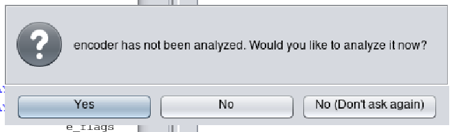
Next, we will open this program up in Ghidra, a reverse engineering tool created and open sourced by the NSA. After opening the binary we are prompted to allow the tool to perform some initial analysis. We will stick with all the default analysis options.
接下来,我们将在 Ghidra 中打开该程序,Ghidra 是 NSA 创建并开源的逆向工程工具。打开二进制文件后,系统会提示我们允许该工具执行一些初始分析。我们将坚持使用所有默认的分析选项。
Ghidra 提示我们分析二进制文件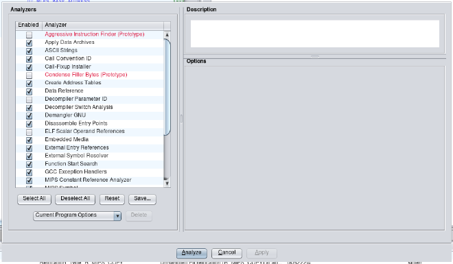
选择默认值并单击“分析”
Once Ghidra finishes its analysis of the binary, we navigate to Search -> For Strings... -> Search. Then we filter for the string /etc/passwd.
Ghidra 完成对二进制文件的分析后,我们导航到Search -> For Strings... -> Search 。然后我们过滤字符串/etc/passwd 。
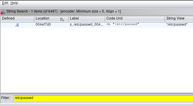
搜索搜索“/etc/passwd”
We see that this string is located in the binary at address 0x004ef7d0. By clicking on this string, the main Ghidra window navigates to that address where see a string reference labeled s_/etc/passwd_004ef7d0. On this string we perform the following navigation: right click -> References -> Show References to s_/etc/passwd_004ef7d0. This will search the binary for any code that references this string.
我们看到该字符串位于二进制文件中的地址 0x004ef7d0 处。通过单击该字符串,Ghidra 主窗口将导航到该地址,在该地址中可以看到标记为s_/etc/passwd_004ef7d0的字符串引用。在此字符串上,我们执行以下导航: right click -> References -> Show References to s_/etc/passwd_004ef7d0 。这将在二进制文件中搜索引用该字符串的任何代码。
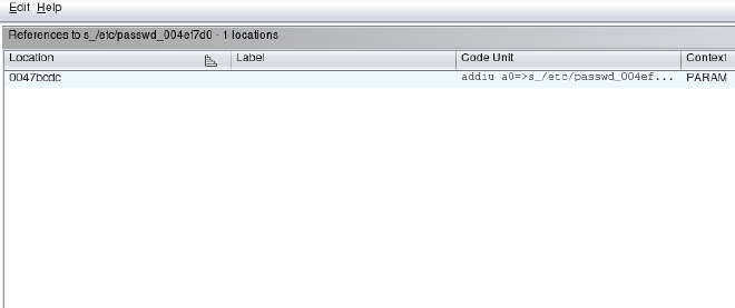
参考搜索 s_/etc/passwd_004ef7d0
The results show a single reference to the string /etc/passwd at address 0x0047bcdc. By clicking on this address, the main Ghidra window navigates to this assembly instruction that references the string and the corresponding function in the decompilation window.
结果显示对地址 0x0047bcdc 处的字符串/etc/passwd的单个引用。通过单击该地址,Ghidra 主窗口将导航到该汇编指令,该指令引用反编译窗口中的字符串和相应的函数。
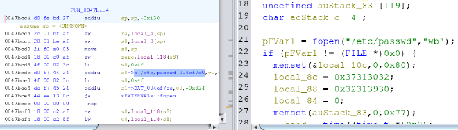
Ghidra 反编译窗口中的 /etc/passwd 参考
The entire function decompiled by Ghidra is as follows:
Ghidra反编译的整个函数如下:
|
|
We can see in the highlighted lines above, the /etc/passwd file is opened in write mode. Then a few local variables are set that look interesting. One reason they look interesting is because local_8c is referenced as being sent into the crypt() function which is responsible for producing password hashes. Another reason they look interesting is because although Ghidra shows us a hex representation of this data, a careful observer would notice that all that hex data is in the printable ASCII range. In fact these lines of code code be rewritten as the following:
我们可以在上面突出显示的行中看到, /etc/passwd文件以写入模式打开。然后设置一些看起来很有趣的局部变量。它们看起来很有趣的原因之一是因为local_8c被引用为发送到crypt()函数,该函数负责生成密码哈希值。它们看起来很有趣的另一个原因是,虽然 Ghidra 向我们展示了该数据的十六进制表示,但细心的观察者会注意到所有这些十六进制数据都在可打印的 ASCII 范围内。实际上这几行代码可以改写如下:
|
|
This clearly looks like a null terminated string. However we need to understand that there is an endianess issue at play. So by reversing the order of the two 4 byte strings, we get 2017 and 0912.
这显然看起来像一个以空字符结尾的字符串。然而我们需要明白,存在一个字节顺序问题。因此,通过颠倒两个 4 字节字符串的顺序,我们得到2017和0912 。
Wait a minute… The administrative username is vstarcam2017. Surely, the developers would not have choosen a password that is the date they were developing this device??
等一下…管理用户名是vstarcam2017 。当然,开发人员不会选择他们开发该设备的日期作为密码?
Let’s attempt to confirm our password with hashcat.
让我们尝试使用 hashcat 确认我们的密码。
echo 'uTV43RfKc73oM' > hash.txt
echo '20170912' > passwd.txt
hashcat -m500 hash.txt passwd.txt
It cracks successfully! 就破解成功了!
UART Login as Root UART 以 root 身份登录
#
Now all we have to do is power cycle the device, allow it to boot up normally and wait for the login prompt.
现在我们要做的就是重新启动设备,使其正常启动并等待登录提示。
We provide the username vstarcam2017 and the password 20170912.
我们提供用户名vstarcam2017和密码20170912 。
veepai login: vstarcam2017
Password:
Nov 28 15:35:16 login[65]: root login on 'console'
[vstarcam2017@veepai:~]# id
uid=0(vstarcam2017) gid=0(root) groups=0(root)

Next Steps 下一步
#
Now that we have a full dump of the firmware and a root shell we have all the tools we need to start looking for software vulnerabilities in various network services running on the device. We can also check the security of the communications the device makes with cloud servers. These are a number of the risks that may get discovered during an IoT pentest.
现在我们已经有了固件的完整转储和 root shell,我们拥有了开始在设备上运行的各种网络服务中查找软件漏洞所需的所有工具。我们还可以检查设备与云服务器之间的通信的安全性。这些是物联网渗透测试期间可能发现的一些风险。
原文始发于Brown Fine Security:Uncovering Hardcoded Root Password in VStarcam CB73 Security Camera
转载请注明:Uncovering Hardcoded Root Password in VStarcam CB73 Security Camera | CTF导航